RESEARCH DEVELOPER KIT - WIRELESS HAPTICS
Hardware
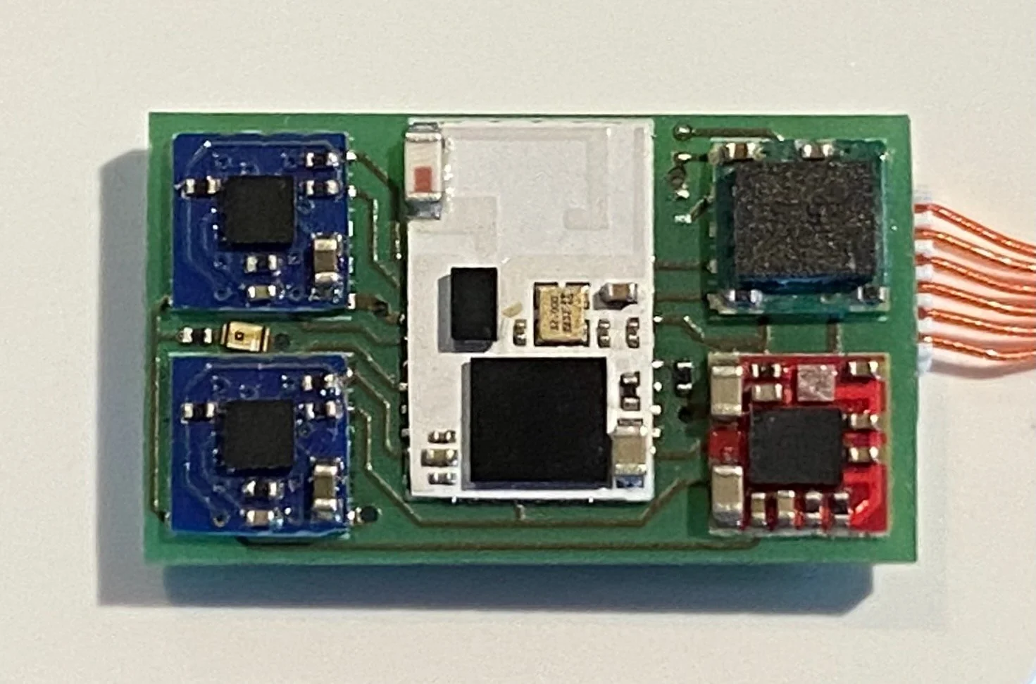
The 10x17 mm main carrier board integrates five tiles:
(1) Core.W - BLE wireless processor core
(1) Power.L.1 - single-cell lithium-ion battery charge monitor and integrated 1.8V system regulator
(1) S1 slot - compatible with all S1-class Sense tiles (default Sense.I.6P)
(2) D1 slots - compatible with any D1-class Drive tile (default two Drive.H)
The back of the carrier board has four JST XSR connectors:
(1) 6-pos programming/debugging header (compatible with the included programming dongle)
(1) 2-pos Li-Ion battery connector
(2) 2-pos D1 actuator outputs
Included in the kit are:
(1) pre-wired Vybronix VG0832013D 8mm-diameter LRA
(2) JST XSR pigtails
Power
SYSTEM POWER: The Power.L.1. tile provides the 1.8V system voltage to the other tiles of the RDK-H. This system voltage is enabled whenever the DEBUG.SWITCH line is left floating and either the battery is present (and sufficiently charged) or 5V is present on the DEBUG.CHG.+ pin. Connect the SWITCH line to CHG.GND to disable the system voltage (connecting the RDK-H to the included programming dongle without connecting the dongle to a power source will automatically ground the SWITCH line). Note that whenever the battery is first connected, you must apply 5V to the CHG.+ pin to wake up the Power.L.1 tile from ship mode.
ACTUATOR POWER: The actuator output voltage for the two D1 slots is supplied directly from the battery. Thus, while you can communicate with all of the tiles without a battery present, it will be necessary to actually drive the actuator(s).
Quick Start
The RDK-H ships with basic validation firmware pre-installed. To get started:
solder a Li-Ion battery to the included pigtails (paying careful attention to the polarity as shown)
attach the battery to the RDK-H
attach the included LRA to the D1.1 output
attach the programming dongle to the debug port
attach the programming dongle to a computer or power supply
After a few seconds, the LEDs of the programming dongle will illuminate, and then the red LED between the two D1 tiles of the RDK-H will begin to blink. While blinking, the Core.W is awake and awaiting a BLE connection. If the LED stops blinking, the Core.W has gone into sleep mode, in which case you will need to power cycle the RDK-H before establishing a connection.
Bluetooth Communications
Using a Bluetooth scanner on a mobile device or computer, search for and connect to the “STM32WBA” device. Once connected, you should see three data services, each with multiple characteristics, as described in the table below. Of particular interest are the following:
SYSTEM.STATUS: The SYSTEM.STATUS characteristic provides a communications check for all of the included tiles:
bit 0 = Power.L.1
bit 1 = S1 slot
bit 2 = D1.1 slot
bit 3 = D1.2 slot
Where a fully-functional RDK-H should return a value of 0x0F (0b00001111).
CONTROL.TRANSIENT_TRIGGER: Writing a value between 1 and 127 will send a request to the DRV2605 LRA driver in the Drive.H tile to play the haptic waveform stored in that location of the internal haptic-effect library.
SENSE.ACCELS: The raw 16-bit accelerometer data from the Sense.I.6P tile is collected every 100ms and presented via the SENSE.ACCELS characteristic.